Using a photocell, resistance can be applied and removed from an audio signal as a light source is switched off and on. The photocell mutes the audio signal when no light is being received. When light is received the resistance from the photocell is removed and the audio signal is no longer muted. By switching the light source on and off in defined intervals the audio signal is formed into rhythms and patterns.
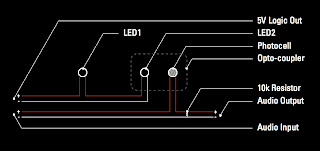
In the circuit diagram below, the audio signal is constant and remains muted until the light source is switched on.
Circuit Diagram:

5V Logic Out: An interface, ie: Arduino or Highly Liquid's MD24, sends 5V out to power LED1 & LED2 on.
LED1: Indicator for when light source is on.
LED2: Coupled with photocell, is on when LED1 is on.
Photocell: Coupled with LED2, when LED2 is off resistance mutes audio signal.
Opto-coupler: Photocell & LED combined acting similar to a switch.
10K Resistor: Pull down resistor which facilitates muting of audio signal.
Audio Input: Source audio signal
Audio Output: Audio signal when LED2 is on, otherwise mute when LED2 is off.
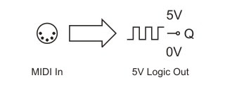
Using Highly Liquid's MD24 (triggers 5V Logic Out using midi messages, ie: notes) & a midi sequencer (ie: MPC 500); a midi note, which corresponds to one the MD24's output pins, can be sent. When this defined midi note is received by the MD24 its corresponding output pin powers LED1 & LED2, which causes the photocell to remove its resistance on the circuit allowing the audio signal to be sent to the audio output. This connection is only made for the duration or pattern of this specific midi note.
Highly Liquid's MD24 Logic Output:
 Highly Liquid's MD24


No comments:
Post a Comment